
example SYSTEMS & INSTALLATIONS
PROCESS FLOW DIAGRAM
For all bulk or powder storage, transfer & processing systems, we start with a Process Flow Diagram (PFD), as per the example shown below.
By producing a PFD, this enables us to define and agree the process, along with the the positions of the components required mechanically & as well as to define the electrical devices and I/O requirements for the overall system, which we can then pass on to our controls integrator.

EXAMPLE INSTALLATIONS
Below are some illustration of systems that have been delivered to clients, either designed and/or installed by JBHMHS contractors and/or our selected specialist sub-suppliers or partners.
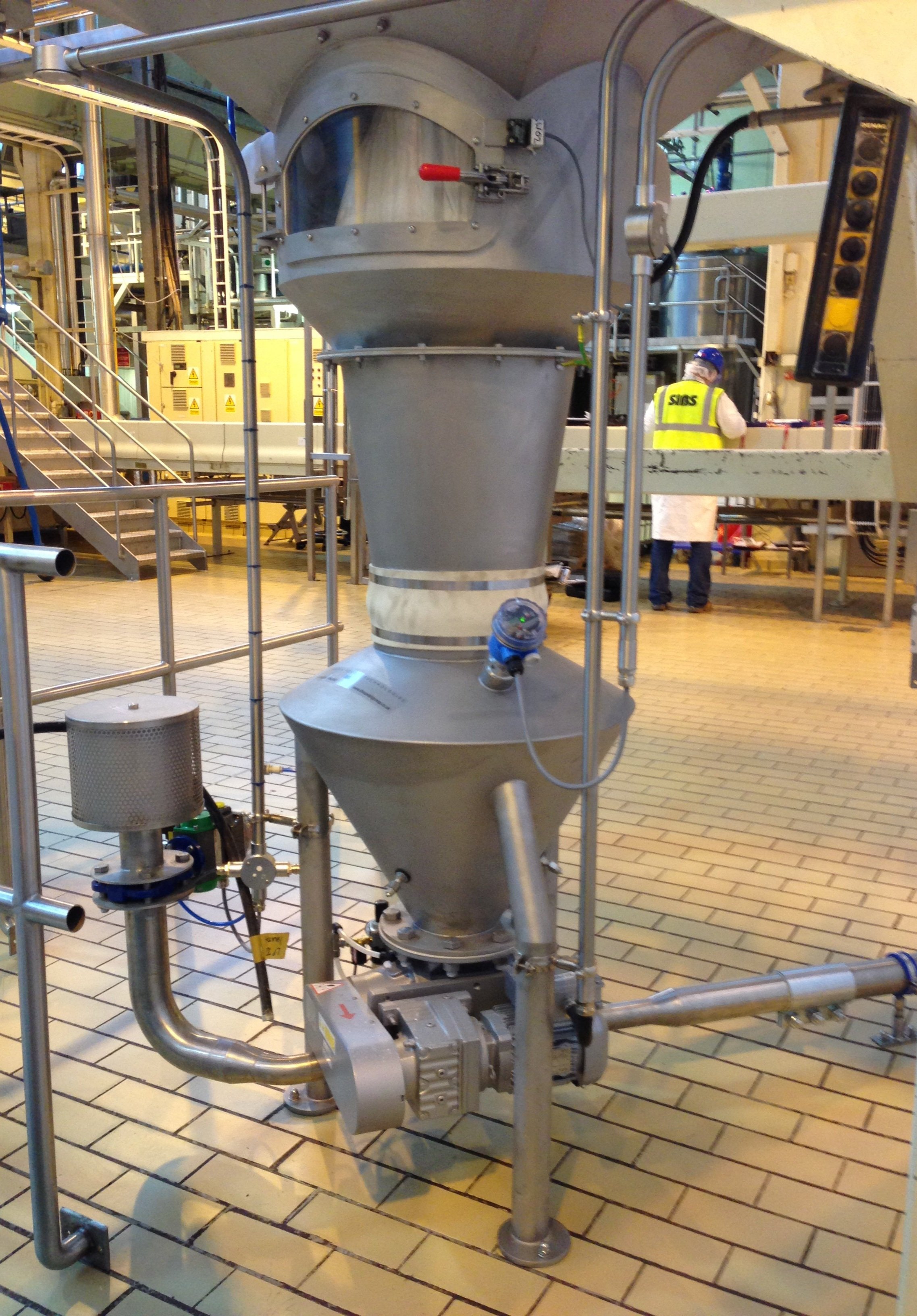
Pneumatic Hopper Extraction System

New Storage Silo for Flour

Storage Tanks for Chemicals
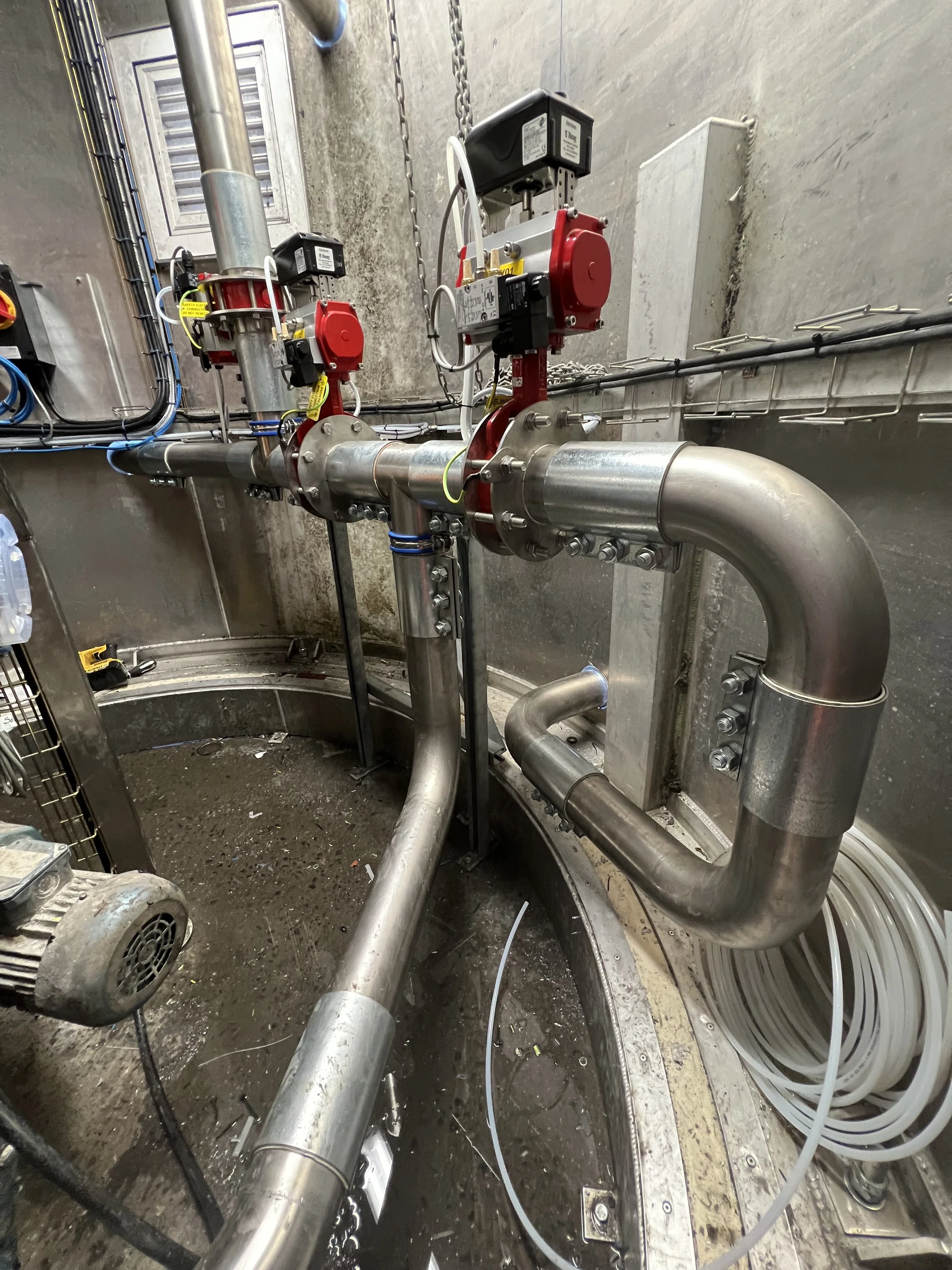
Pneumatic Transfer Pipework

New Rotary Sifter in Flour Silo Base

Fast Acting Explosion Protection Valve

Industrial Mixer on Weigh Platform

External Filter System for Sand Mixing Facility

Fluid Pumping System

Twin Big-Bag Transfer System for Sand

New 20m2 Storage Silo for Silica Sand